Saturday, September 21, 2019

Wltoys 12428b (part 25: Fixing slop in steering)

Setting less terrible toe angles seemed a bit pointless when the wheels kind just point wherever they want anyhow.  So that's the next order of business.

I needed a very thin shim, and after looking at the cost of stock at the hobby shop, i very carefully cut down an aluminum can.  I cut this little strip with a steel straight edge and 4 or 5 passes with a Stanley knife. 

0.16mm thick and ~1.89mm high.
Curiously, a can is about 0.25mm thick at the bottom and 0.12mm thick at the top.  So not only is it free, but we can make shims of different thicknesses!

The idea was to remove the play in this part of the steering mechanism.  I'm hoping a picture tells a thousand words, because i'm not sure i can explain it..

Craft knife points to the shim being inserted from the right.
It took a little fettling to get it to fit, and in the end instead of pushing the shim in, i ended up holding it in place with long nose pliers and moving the normally stationary part onto it (if that makes any sense).  

When it was inserted, I tightly folded the ends over so hopefully it stays in place.

Wltoys 12428b (part 24: Fixing front toe out)

From standard these cars come with a toe out that's quite visible.  When i measured it (I am not an engineer..) it seems about three degrees each side (with the standard fixed, equal length 61mm steering arms).  I did this by:
  1. Placing the car on a piece of paper, aligning it perpendicular.
  2. Place a straight edge along the front wheels, draw a line (the outside ones)
  3. Then rule progressive parallel lines towards the centre until they cross.
  4. At the crossing point, use a protractor to measure the angle.
  5. Halve that number to indicate the toe out for each wheel.
Such science!
Then we need to make up some adjustable steering arms so we can alter the toe.

Attempt 1: I cut the heads off some random bolts and screwed in the spare piston ends from the CVA shocks.  This would have worked, however, they're non adjustable.  Worse, I cut down the only bolts I had, and they were too short.. I really could have gone and got some more, cut them to the exact length.

Attempt 2: Buy some adjustable steering arms.  Ended up getting the Tamiya 54539 Full Turnbuckle Set. I fitted them in the following combination to yield an adjustable arm of nominal length 61mm:

Top: The new parts  Below: The standard 61mm arm.
Long story short, after a bit of mucking around I was able to produce 3 degrees toe in with equal length steering arms of 60.60mm.  That's about as good as I am willing to attempt right now, mainly because there will be wild variations in actual steering because of the play in the plastic steering mechanism.

Friday, September 20, 2019

Wltoys 12428b (part 23: RWD with locked rear diff)

So the rear wheel drive conversion has been very interesting.  Not only has it allowed me to isolate and then optimise the rear end, it's unlocked an entirely different vehicle from the AWD one.

However, one thing was immediately obvious, rear wheel traction was sorely lacking.  Hence, locking the rear diff with BlueTac :)

I kept another diff open, hence labeling.

I did this rather hastily and didn't bother taking any in-progress pictures.  However the process is pretty straight forward:
  1. Remove the wheels and rear differential cover etc.
  2. Remove the differential and axle assembly.
  3. Carefully open the differential by removing the 4 screws.
  4. Carefully note the arrangement of the spider gears.
  5. Carefully remove the spider gears onto a sheet of white paper.
  6. De-grease and clean the spider gears and inside their housing.
  7. Take a wad of BlueTac and shove it into the housing..
  8. Reinstall the spider gears, embedding them in the BlueTac.
  9. Shove more BlueTac on top of the spider gears.  Aim to fill it with only the smallest amount coming out of the screw holes upon re-assembly.
  10. Reassemble the differential, carefully tightening screws.  Don't force it.  If you have not enough then the spider gears will still move.  Too much and it won't go back together properly.  
  11. ..fettle until it works ;)
  12. Reinstall in the reverse order of disassembly.

Road Test:

OMFG.  The thing is a beast. Totally different animal..
  1. It feels more agile, nimble, responsive.  And powerful.
  2. Will readily lift a front wheel under acceleration.
  3. Brake application causes rear wheel lock, done carelessly induces spinout.
  4. Turning circle doesn't seem to be badly impacted.
  5. Can now easily do doughnuts.. ;)

Offroad Test:


Hmmmm... something isn't quite right.  It's nearly uncontrollable on full throttle.. I think it's torque steer?

  1. Whenever the car is at full throttle it will steer to the right (clockwise).
  2. From a standing start it will just do a doughnut, always the same direction.
  3. Trim the steering to the left, under full throttle it will travel straight, and then off throttle will travel to the left.  So i don't think a steering or even a toe issue.
  4. It only appeared to happen when the diff was locked.  RWD with open diff didn't have this issue.
Some interesting information.  Fixes? I'll try adjusting the front toe, that needs doing already.  Failing that I don't mind going back to AWD.  I feel like the rear is solid now which is how this all started in the first place.. ;)

UPDATE 1: Fixed the issues with toe out and steering play, but even on tarmac it still very readily wants to steer to the right.  

Monday, September 16, 2019

Wltoys 12428b (part 22: rear wheel drive conversion)

I was getting some quite serious While i was doing some maintenance

So I was halfway through installing a spare front diff from the parts car when i decided I'd had enough of front diffs and their noise and friction and various wear issues, so I decided on a whim just to pull it out, and the front drive shafts as well:

Front diff and drive shafts notable in their absence.

So although it's dark out, i went up and drove it on the road.  On a LiIon battery in storage mode (~7.4v) and with throttle trim turned right up, the thing absolutely flies.  It's a completely different car!  I'm slightly in awe.

Pros:
  1. It accelerates like a demon, especially on the road (traction)
  2. It's relatively very quiet and the motor noise is much more evident.
  3. It doesn't suffer from power on under-steer.
Cons:
  1. It's really fast.. ;) and i hit the curb more than once :/
  2. The brakes only work on the rear wheels..
  3. Toe out factory front wheel alignment causes tracking issues.
  4. More power through the rear wheels induces wheelspin
  5. The open rear diff servers to accentuate this issue.
  6. The tail-shaft CV joint angles could be improved (noisy).
I do have even more front diffs on order, but i don't know what to do now!

UPDATE: I took it up the hill to play on the dirt and the major limiting factor regarding acceleration is the open rear diff.  You can hear it variously spin up one wheel or the other, and it won't power slide as it lifts the inside wheel and just spins it.

I fixed the CV joint issue by lowering the rear ride height a bit.  Fwiw; for ease of maintenance etc when on the bench I have the car in a cradle (you can see one of the dowels in the above picture).  This means that there is no weight on the wheels and the extra droop causes the CV noise issue.

Possible mods, lock the rear diff and fit adjustable steering arms.

Saturday, September 14, 2019

Wltoys 12428b (part 21: rear suspension geometry changes)

While i was very happy with the CVA shock upgrades, the rear mounting (install ball mounts from standard shocks and install i) left a little to be desired, in that:
  1. Snugging up the top screw placed sideways pressure on the shock top, and i could see whiteness (plastic fatigue) where the shock top joins the cap.
  2. The spring required all the spacers I had and even then the ride height could have been higher.  Upon removal, the spring had compressed.
  3. The shock top mount was non-adjustable.
So, i decided to make up new rear top shock mounts.  Unfortunately, I'm still rather devoid of any actual trained understanding of suspension, but I worked on the following approaches:
  1. Suspension components require compliance (movement) in use.
  2. But mounting points themselves (this part) should be solid.
  3. Parts should not be under any static fatigue when installed.
  4. Parts should not be exposed to any avoidable fatigue in use.
  5. The part should allow adjustment for final positioning and tuning.
  6. Anchor points labelled consistently between designs; A and B (see pics)
  7. Incorporate only parts from the 50519 and 50520 kits, specifically use the "hex ball head connector" (ala tamiya 53968)
  8. For maximum rebound effect, the shock should be as vertical as possible.
  9. The shock should be allowed to always retain it's full travel and not be overly compressed when variously adjusted.
  10. The final assembly should not foul the chassis and/or body in any respect.
  11. Where all the above are satisfied, body roll should be decreased by lowering the center of gravity by not using overly stiff springs or via an equivalent adjustment.
So, that setup, I variously started with some drawings, and then mocked up in cardboard, test fit, then onto test parts (1.6mm aluminum sheet).  The process involved several designs:

Designs are numbered, left to right, top to bottom.
V1 through v5: These were produced on a principle of three anchor points being good and strong (A, B and the 3rd not labelled but it's visible in the part marked v4).  The idea here was to have the suspension mount to one of the line of numbered holes along the edge.  This design was abandoned because ultimately the angle precluded use of the hex ball head connector if mounted directly on the part (a stand off of some sort would have worked)

V6 through 9: Worked on the idea that i needed to be actually able to use the hex ball head connector, so it incorporated proper clearance from the start.  It also reduced the number of mounting points down to two, given that 3 was overkill here.  Adjustment in this design was incorporated by removing the mounting bolt A and rotating the part.  This in turn moved the shock top through an arc.  The precise arc being difficult to determine, hence the incorporation of a separate arm used for positioning (v8), then finally built up in aluminum.  This design was abandoned because making the adjustment was fiddly, and the optimum angle was hard to find.. i felt like i needed more science and the fun factor was waning..

and finally V10: Back to basics.  Two solid chassis mounts (A and B), a single non adjustable mount for the hex ball head connector in a good average position which didn't require spacers and allowed the shock its full travel.  The whole assembly installed using long bolts and using the brass stand off pieces (two of which are missing from this picture):

Two brackets machined together, then one reversed for install.
Finally, installed it all into the car.  In this picture it's clear how the brass standoff tubes have been used to give clearance of the bracket from the chassis, and to move the shock into a more vertical position:

The final part as installed on the car.

Verdict: On the road it feels pretty much the same as before :) but I'm happy that the shock top won't fatigue early, and also that I admire my handwork through the quarter window behind the drivers seat :)

Wednesday, September 04, 2019

Wltoys 12428b (part 20: Oil filled standard rear shocks)

So, I'm very happy with the CVA suspension upgrade.  If i could justify it (and if the parts were available) I'd upgrade the other cars too.  But i can't and they're not.  So what I'm left with is trying to make good on the stock rear suspension.

Negatives:
  1. It's very stiff especially compared to the horizontal front.
  2. Ride height is quite high which accentuates body roll issues
 Positives:
  1. I have multiple spares
  2. Trivial inspection shows all the makings of something better.
NOTE: High precision drafting skills.
I'm not the first person to suggest filling these with oil. There is even a mysterious and seemingly useless little plastic tube (2.55mm x 4.85mm) located exactly where the o-rings would go (as per my recent experience with the CVA shocks).

Option 1: use the standard plastic o ring:

Kevin tells me the oil i needed was around 800cps (which he then retracted and suggested 1000cps).  I have some 750cps, so I've used that.

There's nothing like a categorical No.
Within a heartbeat it all just bubbled out the small end..

Option 2: source proper o rings:

So off to the internet i go to find some appropriate o-rings.. Looking online they're specified using their ID (internal diameter) 2.55mm and their CS or t (cross section) which for me is ~1.1mm (~4.8 - ~2.6/2).  So check out these guys.. this is a list of o-rings of various types .. or some reading on this extensive post suggests these will work

But before i got around to purchasing them..

Option 2a: Use some crappy foam instead of proper o-rings:

..I literally found this on the lab floor, i have no idea where it came from.  It's some kind of foam rubber:

it just .. appeared

I fashioned an o-ring around the shaft of the piston (in place of the small plastic o-ring), and also another around the large end cap.  It worked well enough to see that o-rings won't help..

the second issue is that the springs are very stiff.


Option 2b(?): Cut the springs..


I thought shorter springs = softer.  But it doesn't really seem the case.  It seems they're just .. shorter.  I wish there was more i could say, but even cut they don't seem to be any softer.

Option 3: Just do it properly..

Really.. these just work.  Unless you're on a total shoestring, just do it.

Engineering works..

Wednesday, August 28, 2019

Wltoys 12428b (part 19: Tamiya CVA suspension upgrades)

Well, with the vertical front dampers mod, the front was as hard and bouncy as the rear.  The net effect was a very twitchy car, prone wildly bouncing off minor bumps and over-steering.  Was fun to a point, but I wanted something more controllable.

After a bit of research i discovered much respect for a line of damper kits by Tamiya, the T50519 for the front and T50520 for the rear.  The latter has been discontinued :( but still available online if you hunt around a bit.


These are very versatile parts, and not expensive (around $AU30 each):
  1. They can be built in multiple lengths 
  2. They come with 2 pairs of springs and damper ends
  3. And three different pistons, for soft, medium hard.
  4. Three internal spacers (piston travel, ride height) and three external spacers (preload)
  5. ..and you can then of course use whatever shock oil you like, some is included.
Setup correctly they can match the stock dimensions of the 12428b (in compression and extension) with the exception that they're larger diameter.

Intention:

Given the car is has previously run very hard suspension I'm hoping to achieve a softer ride to see how that feels.  I expect more ground contact (better acceleration & steering) at the cost of body roll (pitch/yaw).  The suspension slightly depresses at rest when under it's own weight and travel is remarkably easier and smoother than with the stock setup.

My front setup:

As I've mentioned, for the front was running my vertical shock mod and the T50519 setup as follows:
  1. The longest spring (for overall length).
  2. The shortest damper end.
  3. The softest piston (the one with three holes in it)
  4. The V7 (thickest) external spacer (for spring preload and to stop the top falling off).
  5. No internal spacers (for longest travel).
  6. The OEM shock ends from the 12428b (they do fit).
  7. Some 750 shock oil i had sitting around.
NOTE: Installation uses the original stainless shock ends

My rear setup: 

The rear shocks went together the same as the front, and were installed (upside down) in the same position as the OEM shocks, no changes required.  I did arrange the shock in the most vertical position.  Setup:
  1. The stiffer spring.
  2. The longest damper end.
  3. The softest piston (the one with three holes in it)
  4. ALL the external spacers i had, including those from the front shocks.
  5. Some closed cell foam rubber on the bottom of the battery tray.
  6. No internal spacers (for longest travel).
  7. The OEM shock ends from the 12428b.
  8. The 750 shock oil i had sitting around.
Even with all those spacers, when allowing for spring compression at rest, the ride height is lower than standard, so the foam rubber acts as a bump stop should it be needed.

It's a shame, but the rear shocks I sourced were possibly the last in Australia :(

Verdict:

This is a completely different vehicle and am very happy with this mod.  Some things I didn't expect and am really happy about:
  1. When dropped on the bench, the solid thud, like a lump of wet clay.
  2. That the unplanned reduction in ride height helped with expected body roll.
  3. That body roll now was SO much more predictable, you can steer it out.
  4. To be able to spend SO much more time at full throttle (hot batteries!).
All in all, this thing is quite awesome :)

Sunday, August 25, 2019

Wltoys 12428b (part 18: plastic wheel with broken centre)


I may have over tightened the wheel nuts..

So i was thinking, i could possibly install a hex in the wheel (covered in cling wrap) and then epoxy the center up again, then drill it out.. wdyt?

UPDATE 1: I did that, well in fact i just super glued the hex in there and bolted it on with a washer.  Given there were cracks all up the arms and i expected it would just shear off given half a chance.  Yeah, so it worked for an hour or so, but then it broke again.


UPDATE 2: Meanwhile I had gone ahead and bought another car purely for spares.  That showed up the day before my fix broke and so i just pinched a rim off that and painted it up etc.

UPDATE 3: I similarly broke one of the plastic bead lock pieces, i suspect from over-tightening combined with blunt trauma.. ;) 

UPDATE 4: We broke two(!) more wheels yesterday.  The issue may have been because i used some threadlock on the wheel nuts, i think it ate the plastic away a bit.  At any rate I just bit the bullet and ordered some metal wheels off Bangood.

Wltoys 12428b (part 17: Arty photograph,,)


..this is literally where the battery died.. pretty? ;)

Sunday, August 18, 2019

Wltoys 12428b (part 16: front suspension geometry changes)

A friend of mine told me James May had taken to "un-pimping" his ride by removing the various "upgrades" and reverting it to standard.  The argument being that those dotards who modify cars aren't automotive engineers and they should stick to what they know.. like playing playstation.

But my friend, nor James, have seen this; it is unquestionably the pinnacle of automotive engineering.  I call it a bent bit of metal taken in nice lighting:

..but what does it do..
But what does it do i hear you ask?  Well, I'm glad.. yep.. it's a shock tower for the WL Toys 12428b.  What's that?  Well what it does is makes the front just as bouncy as the rear.  How is that a good thing?  Well because it looks more spectacular when the front is higher than the rear, the alternative being generally embarrassing.

Note inverted shock.  Also note "in process" manufacturing state.
Inverted shock because the normal way up it won't lean over properly.  To do that you need to take the um balls (the little steel bits at the end of the shock) and swap them over so it fits in upside down.

Insert pseudo science; if a shock is more leany it's less bouncy and more smootherer (ref: youtube).  Also note my new part has multiple adjustments like the pros have.

So, currently the car is running the standard dry shocks, the front is stiffer and the rear uses the standard mounts in the most relaxed position (most leaning forwards). Verdict? Honesly? I have no i idea, was too busy having fun :)

zomg it didn't break!! ;)
UPDATE: Over any kind of bumpy ground and especially when turning, this mod makes the car skip and hop then grip and oversteer and just behave wildly.  I do like it however it has allowed me easy access to the front dampers which when upgraded should prove useful.

Thursday, August 15, 2019

Wltoys 12428b (part 15: it didn't break ;))

Charged up both batteries today and went for a walk with the white one.  It was lovely :) ..i feel compelled to talk all about it yet i really don't want to spoil the memory by putting words to it.


..but it's a bit hard not to.  There's certainly an amount of bonding that's going on here.

.. oh go on ..


he he he... ;)

Trackbot (part 3: arduino integration and control code)

So with the microbit sending HIGH to some jumpers, and an arduino setup to control the lego motors, time came to integrate them together.  I brought over four wires from the microbit; forward and reverse for each track.

My plan there was to just connect all four jumpers from the microbit to the analog input pins on the arduino.  This turned out to be trivially easy, in the code i just run analogread() for each pin and if the input is above a threshold, assume it's a signal and do something.

Connecting microbit to Arduino analog input pins.
We're then getting pretty close to having it working.  It took a few iterations in the arduino code before i settled on the following, one for each track:

const int pwmOutput = 255;  
const int moveThreshold = 125; // how much of a signal before we trigger  
// left  
if (analogRead(leftFord) > moveThreshold){  
   moveLeftFord(pwmOutput);  
} else if (analogRead(leftBack) > moveThreshold){  
   moveLeftBack(pwmOutput);  
} else stopLeft();  

This was probably the most time consuming element in the project.  I wanted the vehicle to only move if you were holding the button down, otherwise stop that motor.  I'd already tested and the microbit will happily accept multiple simultaneous commands, so we're all good.

So with the wires etc all bundled on top I drove around a bit and scared the cat :) job done, it's now just a matter of packaging it all up so that it's neat and tidy and kid proof.  I should also add some fun factor in, and with four more potential inputs on the controller i could add some sounds or lights or a gatling gun.. whatever is the most enjoyable.. ;)

Trackbot (part 2: remote control with microbit bluetooth)

Again there was no specific plan here, just worked it out as i went along, meanwhile holding true to these objectives:
  1. Ideally, don't spend any money (use what i have already)
  2. Be able to control forward and reverse for each track.
  3. In case of having to spend money, make any spend as reusable as possible.
  4. Make it fun to use!  Lights!  Buzzers!
A commercial RC control was a non-starter due to rule number 1.  That being said i did find a nice tutorial about how to integrate one with an Arduino.

Next, i did have the two BBC micro-bit microcontrollers, and i knew that they both did bluetooth.  So i had an idea i could build up one as a transmitter/controller and the other as the receiver.  It turns out getting them talking isn't hard (at all) but i didn't want to use block code, nor even that online compiler thing.

So then i did some reading and discovered there are heaps of choices when it comes to where you code your microbit, including the Arduino IDE.  I had a wow moment at that point :) and quickly dipped into the wonderful world of microbit with the arduino ide thanks to Adafruit.  That short tutorial series completely changed my plans, and i learned:
  1. With the right resources we can achieve amazing things!
  2. That i can easily code microbit in the familiar arduino IDE ecosystem.
  3. When doing so i don't need to sacrifice core microbit functionality (like bluetooth or the other sensors etc).
  4. I don't need two microbits at all, because Adafruit has a BRILLIANT iOS app, and i can control the microbit from there!
  5. wow!
So.. that was a bit if a whirlwind, but as a result i then had a microbit with some wires hanging off it, some code largely based off the example, and an app with which i could trigger the microbit, it was perfect for my needs.

Microbit plus jumpers and power cable (to battery terminal).
I was able to then use the remote control app and hit a button, and the microbit would send one of those pins high.  I randomly picked them, but tested each pin in turn until they all worked.  Also soldering to a microbit is annoying.


I know I'm glossing over things a bit, but seriously that tutorial was awesome, go have a look.  So in essence my remote control setup works as follows:
  1. I power up the L298N which provides 5v to the Arduino
  2. The microbit is powered from the 3.3v supply on the arduino
  3. The microbit is paired with my iPhone
  4. I open the app, connect to the microbit and navigate to the Control Pad
  5. Hit one of the 4 numbered buttons, and one of those jumpers goes high.
  6. ..celebrate.  It was almost too easy.
I do note that i lost PWM control here, these are simply on and off signals.  I can deal with that, and can still code in some soft start stuff if i want.
 
Next is then coding the arduino to do sensible things with these inputs..

Trackbot (part 1: assembing parts, hatching a plan)

I had some parts laying around and I figured i could probably turn all this into something fun for me to make, and fun for my boy to play with. 
  1. The tracks etc from the Lego Technic excavator (42006)
  2. A couple of Lego Technic motors and some cogs to gear them down a bit
  3. A few Lego power cables including a couple of the ones for lights (8870)
  4. An arduino Uno clone (Freetronics eleven)
  5. Two BBC microbit microcontrollers
  6. An L298N motor driver board (these things are neat!)
  7. A 6s NiMh battery pack (9.6v) with Tamiya RC connector
  8. A potentiometer, various jumper wires, a random DC motor etc 
  9. And Ben's oscilloscope which needs using before i have to give it back.

I didn't have a perfectly crafted plan, but it was something like this:
  1. Remember how to drive a DC motor using the L298N with PWM
  2. Work out how the wiring works for Lego motors and how to connect them to the L298N without cutting their cables (because they're expensive).
  3. Work out how to control an arduino remotely.
  4. Shove it all on the tracks and make an remote controlled .. thing.
After sorting out power to the Arduino (using the 5v output from the L298N), the first thing was to hook up the random dc motor to the driver board (tutorial elsewhere) and use the potentiometer to control the PWM input.  Next was to hook in the Lego motors, which required understanding how they were cabled:

Cut these *before* you find out how much they cost.
To connect the Lego motor to the L298N i created some cables as above by cutting the 8870 cables and soldering jumpers into c1 and c2 (you don't need GND or 9v).  The standard motors can now plug into the Lego end and c1 and c2 go to the screw terminals on the L298N. 

Quite nerdy spaghetti.

The code* worked ok, so I then moved on to the tracks themselves. I already had this layout from when I'd been mucking around with the tracks as a Lego project.  There's one engine per track, and for forward travel obviously they'll be rotating in opposite directions.  I just needed to install the battery somewhere and luckily it just fit right in there..
The tracks; one motor for each track and battery pack


And again from awhile ago, I'd gear the motors down so they can run at full speed and provide slow powerful motive force, all the torque etc:

Two stage reduction gears.
Finally i kinda just stuck it all together and it worked, but there was zero consideration given to the packaging, so I couldn't actually drive it anywhere, and there was no control beyond the potentiometer (driving both tracks, one way only).

So next was do work out how to do the remote control, and that was a bit more interesting..

Monday, August 12, 2019

PWM, DC motors and EMI.

So I have some 9v Lego DC motors laying around and also some tracks from a Technic excavator (42006).  Also i have an arduino and lo and behold what just arrived in the post but a L298N motor driver board.. ;)  Basically, I plugged it all together ala a tutorial and it works as advertised.  Only difference is my power source is a 9.6v NiMH battery pack and I'm not using a button.  fwiw code here.

Then i connected the PWM outputs of my arduino to Ben's Oscilliscope (Rigol DS1102E), i can see we're generating a good PWM signal (between ground and IN1):


But when i connect a DC motor to the output terminals on the L298N board, i my nice PWM waveform gets a HEAP of interference, i can only assume it's coming back from the DC motor somehow:


A quick google revealed that this is a common problem caused by Electro Magnetic Interference (EMI) and may be resolved by installing capacitors between the motor terminals.


Saturday, August 10, 2019

Wltoys 12428b (part 14: suspension lubrication)

A quick update, the rear shocks were making a bit of a rubbing noise and weren't traveling smoothly.  I just pulled them down and added some silicon lubricant inside.  I'll try and get some M3 o-rings and do that hack another time:


Thursday, August 08, 2019

Wltoys 12428b (part 13: hunting drivetrain vibration)

Since i put the front diff back in the car really felt as though it was running with the brakes on.  Even on the bench, it seemed to take more throttle to just get the wheels moving.  Looking at the drive-train rotating, there was clearly some oscillation there that wasn't ideal.  It was evident most on the central shaft behind the front diff.

So .. started pulling it all apart again. Because it was easy, I tested with the rear diff removed and it was clear the problem wasn't there.  Then I thought it was my front diff fix (upgrade 12T driving gear and Then Cup to accept M3).  And although my drilling wasn't perfectly straight, it shouldn't have caused the driving gear to rotate out of true of the bearing:

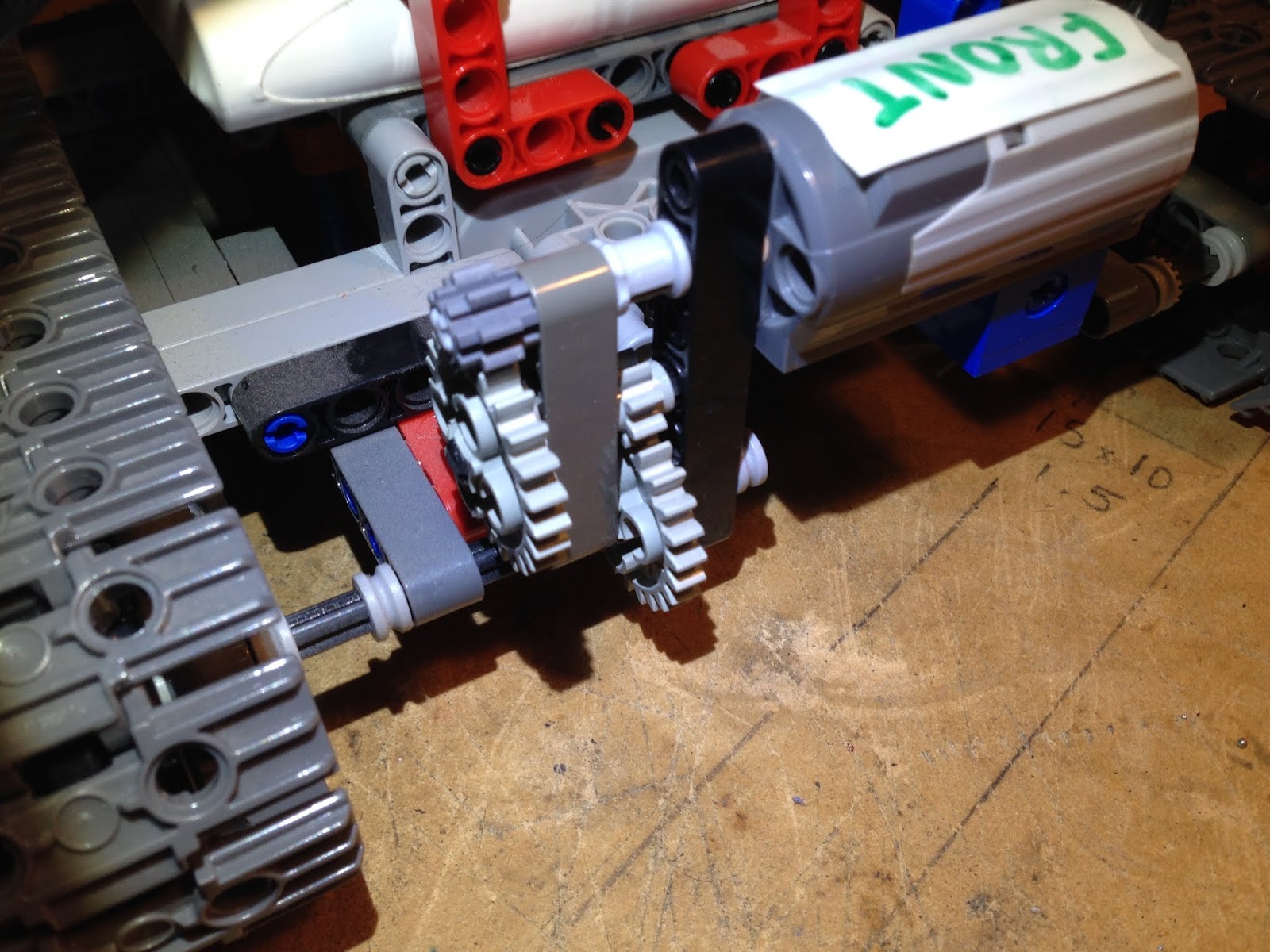
This to remind me which way the front dif goes.. ;)
..but with the front diff removed and the center shaft flapping in the air, still the noises.  So i very carefully ran the car with the large center reduction gear exposed:
Note screwdrivers to stop shafts flying around the place..
And even at that point it was evident that there was oscillation.  No issue with the motor and reduction gears or the little silver bearings, but the shaft the reduction gear sits on (reduction pinion (0084)) isn't true.

Reduction gear with universal joints, front (left) and rear (right).
So I have two issues here.   0084 may be bent(?). And with everything open it became clear that both the universal joints are noisy, especially the rear one which has slop in just about every direction.


So what to do..?  I pulled the springs and pins etc out of the universal joins (how intricate and amazing are they?!) and filleditfullofgreaseandputitbacktogether.  What?  yes.  I may have just made a dirty greasy muck trap for later on, but for right now .. it's quiet.  Which helps finding where other noises are coming from.  Not that there's anywhere left really..

..put back together, pulled it apart.  Not a nice set of noises.  I'm getting a metal vs plastic grinding.  Current guess is a bent 0084. PS: I didn't do anything on the 0084 theory because.. 

UPDATE: for reasons i had the rear of the car apart again and i found something very significant!  If i "over" tighten the 4 screws holding the rear diff on then they compress the housing and it causes the diff to bind and make a not very nice noises.  I ended up adding thin washers between the two halves of the diff and when tightened up it ran smooth.  Gaps in the housing i sealed up with silicone.

NOTE TO SELF, INSERT PICTURE HERE

UPDATE 2: Same same in the front!!! Ended up making a thin cardboard gasket between the front and rear halves of the front diff housing and again that fixed the issue there in that it's much quieter now, for now.. :)

NOTE TO SELF, INSERT PICTURE HERE

Tuesday, August 06, 2019

Wltoys 12428b (part 12: shopping for parts online)

I am sure there's an art to this and I'm not quite sure if i have it down pat as yet.  Have been shopping online a bit lately and have had instances of each of the following scenarios:
  1. Item delivered on time, all good.
  2. Item delivered on time, but found to be faulty.  Refund issued.
  3. Wrong item delivered.
  4. Item not delivered (not sure if that relates to the wrong item above).
  5. Waiting a long time so you're not sure what you're waiting on.. 
  6. Item not actually available, sorry it's on backorder :/
Mind you, i did just do a bit of choose the lowest price + postage in AU, so maybe i deserve what i get.  That being said, while i wait for my "Then Cups", i wanted to collate a list of my mistakes thus far.  So, my amateur insight polished up as a cheap pro tips:
  1. Get the actual proper part number, in this case it's wl12428-0081
  2. Do a search on that, not some other weird description like "Then Cup"
  3. From the set of returns exclude any not in AU (use site:au at the end of the query)
  4. Evaluate their professionalism by some vague indeterminate metrics.
  5. Roll the die..
And thusly a list of suppliers of the wl12428-0081 part, ranked by um, yeah:
  1. http://www.worldhobbies.com.au/front-diff-outdrive-cup-then-cup
  2. https://www.alburyrcmodels.com.au/front-diff-outdrive-cup-then-cup
  3. http://www.modelengines.com.au/front-diff-outdrive-cup-then-cup
  4. https://www.supercheaphobbies.com.au/store/front-diff-outdrive-then-p-24100.html
  5. http://www.acehobbyaustralia.com.au/ which is reporting "503: Service Unavailable" so guess who's last.
So getting meta for a moment, isn't it curious how most of these sites use EXACTLY the same url, it's like they're not only using the same site, but the same data feed as well.

Sunday, August 04, 2019

Quick review of Lipo Battery Low Voltage Alarm

These little RC Lipo Battery Low Voltage Alarm 1-8S Buzzer Indicator Checker Tester LED AZ nifties are pretty awesome.  I can't say this is an original discovery; i saw them on ebay.  The idea is you attach them somewhere on your
RC device, i zip tied mine to the battery hold down arm:


..and they'll give you a constant readout cycling between each cell voltage and a total voltage.  The bonus is you can set an alarm to beep at you when it falls below a set voltage, note; it's REALLY loud.

It's not without it's annoyances, in the end i disabled the alarm and just kept an eye on the display.  I think they could go one up on this device and also add a temperature monitor and probe; but still, i think it's awesome for AU$4.

Wltoys 12428b (part 11: fixing rear diff failure)

So we have two of these cars.  Up until now I'd been writing about the first car, which is now in the process of being painted white.  The second car came out of the box the other day, and taking both batteries we went and ran it just now.  Such fun!! Reuben had a great time, which after all, what this all about; having fun.
..but on the way home, both batteries near dead, having bounced it all over the place and tumbled here and there and generally had an awesome time, we're literally rolling downhill on the way home and i was thinking it was making a bit of a strange noise.. Suddenly the tail shaft just drops right out on the footpath, nice as you like..
Pan head broke off inside the
Upon inspection i can immediately see it's the same bolt that broke in the front on the white car.. The now infamous 0109 "Pan Head (m2x8)", which this time now broke inside the 0085 "Active rear axle pinion" at the rear:

Pan head bolts.. why do you keep breaking?
The thing is, i can't see how these parts are loaded, moreover I don't think we were abusing the car.. It's not like we were doing jumps or whatever..  So I've now gone and ordered the 0085 "Active rear axle pinion" and some extra m2x8 bolts from Super Cheap Hobbies.

However I'm in the mind to drill these out to m3 and put a proper bolt in there..

 ..some days later i got tired of waiting for parts and I did exactly that.  First I had to drill out the grub screws to release the 0085 from the sub-assembly.  Then on the drill press I drilled out the old bolt with a 2.5mm bit, then tapped it out to M3.

0085 in the bench vice ready for tapping to M3
Then test re-assembled everything using an M3x8 hex head bolt, all good. 

The remnants of a grub screw next to the repaired assembly.
Finally all the bolts and grub screws were lock-tighted back in after final assembly.  Works a treat! and now i can await the delivery of the parts i don't need.

Saturday, August 03, 2019

Wltoys 12428b (part 10: painting)

So now the car is out for awhile I'll take the opportunity to paint it.  There are many screws holding the various body panels to the body frame, and after awhile with the electric screwdriver, the parts are in a pile.  Same same taking the bead locks of the wheels:


I decided to leave a black patch on the bonnet because it's racy ;) I just used some painters masking tape to leave the standard faux-carbon panel there.


.. when it's nice outside I'll paint it up I painted it, but it's like 3 degrees C out, so now the study smells like paint.  Still.. it's somehow awesome anyway ;)

Pro Tip: Using the car's packaging as a spray booth ;)
I ended up doing the wheels as well.  All back together and I think it looks awesome! :) really goes well with that blue anodizing.


POSTSCRIPT: In heindsight i scrimped on the surface preparation.  I didn't sand or even prepsol the surface at all.  So when after a few runs the paint started coming off in flakes, I only had myself to blame:

The result is a function of the preparation.. or however it goes..
So! I wire brushed it all off, then sanded it etc etc..

Effort makes the world go around..?
And currently it's looking good.. :)

Wltoys 12428b (part 9: lubricating differentials)

I read somewhere that the metal differentials on these cars come a little dry, and it's true.  It's not a big deal to pull out the various screws to be able to access the rear diff and to apply some machine grease.  It's all shown in the exploded parts diagram for the diff and comes apart easily enough: 

Exploded diagrams are goooood.  It's SO nice having a proper car..

Ensure you also lubricate the gears inside the differential, there's another four screws to access those.

Rear diff in carrier, ready for reinstall.

NOTE: When reinstalling Be sure to orient the diff the correct way in the carrier lest your rear wheels will drive in the wrong direction.  I did that .. ;) also note that you align the bearings on the axle with their housings within the diff carrier.  It's pretty straight forward.

Lubricating the front: getting access to the front diff is pretty straight forward.  After removing the body, invert the car and remove the bash plate, front bumper and the long bolts holding on the lower control arms.  After that it all drops away and you can remove the front diff cover:

Note the orientation of the diff, don't put it in backwards!